
- Differences between U.S. National and International Rules and Procedures
- The air traffic rules and procedures applicable to air traffic in U.S. Class A, B, C, D and E airspace conform with Annexes 2 and 11 to the Convention on International Civil Aviation and to those portions applicable to aircraft in the Procedures for Air Navigation Services – Rules of the Air and Air Traffic Services (Doc 4444 – RAC/501/10) and to the Regional Supplementary Procedures (DOC 7030) applicable to the NAM, NAT, CAR and PAC Regions, except as noted in the cases below. All differences have been registered with the International Civil Aviation Organization.
- Airport Operations
- General
- Increased traffic congestion, aircraft in climb and descent attitudes, and pilots preoccupation with cockpit duties are some factors that increase the hazardous accident potential near the airport. The situation is further compounded when the weather is marginal; that is, just meeting VFR requirements. Pilots must be particularly alert when operating in the vicinity of an airport. This section defines some rules, practices, and procedures that pilots should be familiar with, and adhere to, for safe airport operations.
- Each airport operator regularly serving scheduled air carriers has put into use security measures designed to prevent or deter unauthorized persons from having access to “Air Operations Area.” The “Air Operations Area” means any area of the airport used or intended to be used for landing, takeoff, or surface maneuvering of aircraft. Pilots are encouraged to obtain airport security instructions by posted signs or radio communication.
- General
- Airports With an Operating Control Tower
- Towers have been established to provide for a safe, orderly, and expeditious flow of traffic on and in the vicinity of an airport. When the responsibility has been so delegated, towers also provide for the separation of IFR aircraft in the terminal areas (Approach Control).
- When operating at an airport where traffic control is being exercised by a control tower, pilots are required to maintain two-way radio contact with the tower while operating within the Class B, Class C, and Class D surface area unless the tower authorizes otherwise. Initial callup should be made about 15 miles from the airport. Unless there is a good reason to leave the tower frequency before exiting the Class B, Class C, and Class D surface area, it is a good operating practice to remain on the tower frequency for the purpose of receiving traffic information. In the interest of reducing tower frequency congestion, pilots are reminded that it is not necessary to request permission to leave the tower frequency once outside of Class B, Class C, and Class D surface area. Not all airports with an operating control tower will have Class D airspace. These airports do not have weather reporting which is a requirement for surface-based controlled airspace, previously known as a control zone. The controlled airspace over these airports will normally begin at 700 feet or 1,200 feet above ground level and can be determined from the visual aeronautical charts. Pilots are expected to use good operating practices and communicate with the control tower as described in this section.
- When necessary, the tower controller will issue clearances or other information for aircraft to generally follow the desired flight path (traffic pattern) when flying in the Class D airspace, and the proper taxi routes when operating on the ground. If not otherwise authorized or directed by the tower, pilots approach to land in an airplane must circle the airport to the left, and pilots approaching to land in a helicopter must avoid the flow of fixed-wing traffic. However, an appropriate clearance must be received from the tower before landing.
- The following terminology for the various components of a traffic pattern has been adopted as standard for use by control towers and pilots:
- Upwind leg. A flight path parallel to the landing runway in the direction of landing.
- Crosswind leg. A flight path at right angles to the landing runway off its takeoff end.
- Downwind leg. A flight path parallel to the landing runway in the opposite direction of landing.
- Base leg. A flight path at right angles to the landing runway off its approach end and extending from the downwind leg to the intersection of the extended runway centerline.
- Final approach. A flight path in the direction of landing along the extended runway centerline from the base leg to the runway.
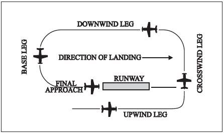
NOTE-
FIG ENR 1.1-1 is intended only to illustrate terminology used in identifying various components of a traffic pattern. It should not be used as a reference or guide on how to enter a traffic pattern.
- Many towers are equipped with a tower radar display. The radar uses are intended to enhance the effectiveness and efficiency of the local control, or tower, position. They are not intended to provide radar services or benefits to pilots except as they may accrue through a more efficient tower operation. The four basic uses are:
- To determine an aircraft’s exact location. This is accomplished by radar identifying the VFR aircraft through any of the techniques available to a radar position; such as, having the aircraft ident. Once identified, the aircraft’s position and spatial relationship to other aircraft can be quickly determined, and standard instructions regarding VFR operation in the aircraft traffic area will be issued. Once initial radar identification of a VFR aircraft has been established and the appropriate instructions have been issued, radar monitoring may be discontinued; the reason being that the local controller’s primary means of surveillance in VFR conditions is usually scanning the airport and local area.
- To provide radar traffic advisories. Radar traffic advisories may be provided to the extent that the local controller is able to monitor the radar display. Local control has primary control responsibilities to the aircraft operating on the runways which will normally supersede radar monitoring duties.
- To provide a direction or suggested heading. The local controller may provide pilots flying VFR with generalized instructions which will facilitate operations; e.g., “PROCEED SOUTHWEST BOUND, ENTER A RIGHT DOWNWIND RUNWAY THREE ZERO;” or provide a suggested heading to establish radar identification or as an advisory aid to navigation; e.g., “SUGGESTED HEADING TWO TWO ZERO, FOR RADAR IDENTIFICATION.” In both cases, the instructions are advisory aids to the pilot flying VFR and are not radar vectors. PILOTS HAVE COMPLETE DISCRETION REGARDING ACCEPTANCE OF THE SUGGESTED HEADING OR DIRECTION AND HAVE SOLE RESPONSIBILITY FOR SEEING AND AVOIDING OTHER AIRCRAFT.
- To provide information and instructions to aircraft operating within Class D airspace. In an example of this situation, the local controller would use the radar to advise a pilot on an extended downwind when to turn base leg.
NOTE-
The above tower radar applications are intended to augment the standard functions of the local control position. There is no controller requirement to maintain constant radar identification and, in fact, such a requirement could compromise the local controller’s ability to visually scan the airport and local area to meet FAA responsibilities to the aircraft operating on the runways and within Class D airspace. Normally, pilots will not be advised of being in radar contact since that continued status cannot be guaranteed and since the purpose of the radar identification is not to establish a link for the provision of radar services.
- A few of the radar-equipped towers are authorized to use the radar to ensure separation between aircraft in specific situations, while still others may function as limited radar approach controls. The various radar uses are strictly a function of FAA operational need. The facilities may be indistinguishable to pilots since they are all referred to as tower and no publication lists the degree of radar use. THEREFORE, WHEN IN COMMUNICATION WITH A TOWER CONTROLLER WHO MAY HAVE RADAR AVAILABLE, DO NOT ASSUME THAT CONSTANT RADAR MONITORING AND COMPLETE ATC RADAR SERVICES ARE BEING PROVIDED.
- Traffic Patterns
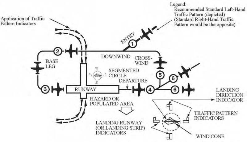
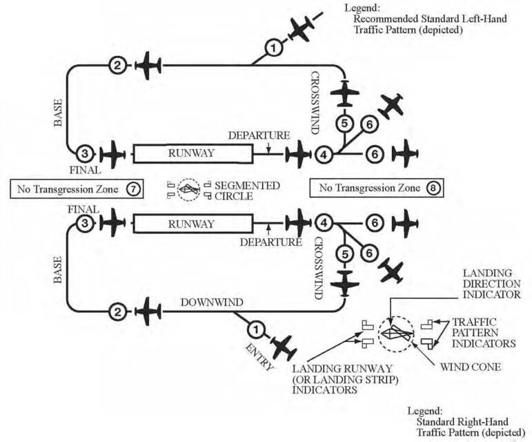
- It is recommended that aircraft enter the airport traffic pattern at one of the following altitudes listed below. These altitudes should be maintained unless another traffic pattern altitude is published in the Chart Supplement or unless otherwise required by the applicable distance from cloud criteria (14 CFR Section 91.155). (See FIG ENR 1.1-2 and FIG ENR 1.1-3.):
- Propeller-driven aircraft enter the traffic pattern at 1,000 feet above ground level (AGL).
- Large and turbine-powered aircraft enter the traffic pattern at an altitude of not less than 1,500 feet AGL or 500 feet above the established pattern altitude.
- Helicopters operating in the traffic pattern may fly a pattern similar to the fixed-wing aircraft pattern, but at a lower altitude (500 AGL) and closer to the runway. This pattern may be on the opposite side of the runway from fixed-wing traffic when airspeed requires or for practice power-off landings (autorotation) and if local policy permits. Landings not to the runway must avoid the flow of fixed wing traffic.
- A pilot may vary the size of the traffic pattern depending on the aircraft’s performance characteristics. Pilots of en route aircraft should be constantly alert for aircraft in traffic patterns and avoid these areas whenever possible.
- Unless otherwise indicated, all turns in the traffic pattern must be made to the left, except for helicopters, as applicable.
- On Sectional, Aeronautical, and VFR Terminal Area Charts, right traffic patterns are indicated at public-use and joint-use airports with the abbreviation “RP” (for Right Pattern), followed by the appropriate runway number(s) at the bottom of the airport data block.
EXAMPLE-
RP 9, 18, 22R
NOTE-
- Pilots are encouraged to use the standard traffic pattern. However, those pilots who choose to execute a straight-in approach, maneuvering for and execution of the approach should not disrupt the flow of arriving and departing traffic. Likewise, pilots operating in the traffic pattern should be alert at all times for aircraft executing straight-in approaches.
REFERENCE-
AC 90-66B, Non-Towered Airport Flight Operations
- *RP indicates special conditions exist and refers pilots to the Chart Supplement.
- Right traffic patterns are not shown at airports with full-time control towers.
- Pilots are encouraged to use the standard traffic pattern. However, those pilots who choose to execute a straight-in approach, maneuvering for and execution of the approach should not disrupt the flow of arriving and departing traffic. Likewise, pilots operating in the traffic pattern should be alert at all times for aircraft executing straight-in approaches.
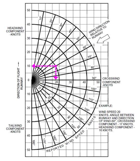
- Wind conditions affect all airplanes in varying degrees. FIG ENR 1.1-4 is an example of a chart used to determine the headwind, crosswind, and tailwind components based on wind direction and velocity relative to the runway. Pilots should refer to similar information provided by the aircraft manufacturer when determining these wind components.
- Unexpected Maneuvers in the Airport Traffic Pattern
- There have been several incidents in the vicinity of controlled airports that were caused primarily by aircraft executing unexpected maneuvers. ATC service is based upon observed or known traffic and airport conditions. Controllers establish the sequence of arriving and departing aircraft by requiring them to adjust flight as necessary to achieve proper spacing. These adjustments can only be based on observed traffic, accurate pilot reports, and anticipated aircraft maneuvers. Pilots are expected to cooperate so as to preclude disruption of traffic flow or creation of conflicting patterns. The pilot in command of an aircraft is directly responsible for and is the final authority as to the operation of that aircraft.
- On occasion it may be necessary for pilots to maneuver their aircraft to maintain spacing with the traffic they have been sequenced to follow. The controller can anticipate minor maneuvering such as shallow “S” turns. The controller cannot, however, anticipate a major maneuver such as a 360-degree turn. If a pilot makes a 360-degree turn after obtaining a landing sequence, the result is usually a gap in the landing interval and more importantly it causes a chain reaction which may result in a conflict with following traffic and interruption of the sequence established by the tower or approach controller. Should a pilot decide to make maneuvering turns to maintain spacing behind a preceding aircraft, the pilot should always advise the controller if at all possible. Except when requested by the controller or in emergency situations, a 360-degree turn should never be executed in the traffic pattern or when receiving radar service without first advising the controller.
EXAMPLE-
KEY TO TRAFFIC PATTERN OPERATIONS- Enter pattern in level flight, abeam the midpoint of the runway, at pattern altitude.
- Maintain pattern altitude until abeam approach end of the landing runway on downwind leg.
- Complete turn to final at least 1/4 mile from the runway.
- Continue straight ahead until beyond departure end of runway.
- If remaining in the traffic pattern, commence turn to crosswind leg beyond the departure end of the runway within 300 feet of pattern altitude.
- If departing the traffic pattern, continue straight out, or exit with a 45 degree turn (to the left when in a left-hand traffic pattern; to the right when in a right-hand traffic pattern) beyond the departure end of the runway, after reaching pattern altitude.
- Do not overshoot final or continue on a track which will penetrate the final approach of the parallel runway.
- Do not continue on a track which will penetrate the departure path of the parallel runway.
- It is recommended that aircraft enter the airport traffic pattern at one of the following altitudes listed below. These altitudes should be maintained unless another traffic pattern altitude is published in the Chart Supplement or unless otherwise required by the applicable distance from cloud criteria (14 CFR Section 91.155). (See FIG ENR 1.1-2 and FIG ENR 1.1-3.):
- Visual Indicators at Airports Without an Operating Control Tower
- At those airports without an operating control tower, a segmented circle visual indicator system, if installed, is designed to provide traffic pattern information. The segmented circle system consists of the following components:
- The Segmented Circle. Located in a position affording maximum visibility to pilots in the air and on the ground and providing a centralized location for other elements of the system.
- The Wind Direction Indicator. A wind cone, wind sock, or wind tee installed near the operational runway to indicate wind direction. The large end of the wind cone/wind sock points into the wind as does the large end (cross bar) of the wind tee. In lieu of a tetrahedron and where a wind sock or wind cone is collocated with a wind tee, the wind tee may be manually aligned with the runway in use to indicate landing direction. These signaling devices may be located in the center of the segmented circle and may be lighted for night use. Pilots are cautioned against using a tetrahedron to indicate wind direction.
- The Landing Direction Indicator. A tetrahedron is installed when conditions at the airport warrant its use. It may be used to indicate the direction of landings and takeoffs. A tetrahedron may be located at the center of a segmented circle and may be lighted for night operations. The small end of the tetrahedron points in the direction of landing. Pilots are cautioned against using a tetrahedron for any purpose other than as an indicator of landing direction. Further, pilots should use extreme caution when making runway selection by use of a tetrahedron in very light or calm wind conditions as the tetrahedron may not be aligned with the designated calm-wind runway. At airports with control towers, the tetrahedron should only be referenced when the control tower is not in operation. Tower instructions supersede tetrahedron indications.
- Landing Strip Indicators. Installed in pairs as shown in the segmented circle diagram, and used to show the alignment of landing strips.
- Traffic Pattern Indicators. Arranged in pairs in conjunction with landing strip indicators and used to indicate the direction of turns when there is a variation from the normal left traffic pattern. If there is no segmented circle installed at the airport, traffic pattern indicators may be installed on or near the end of the runway.
- Preparatory to landing at an airport without a control tower, or when the control tower is not in operation, the pilot should concern himself with the indicator for the approach end of the runway to be used. When approaching for landing, all turns must be made to the left unless a traffic pattern indicator indicates that turns should be made to the right. If the pilot will mentally enlarge the indicator for the runway to be used, the base and final approach legs of the traffic pattern to be flown immediately become apparent. Similar treatment of the indicator at the departure end of the runway will clearly indicate the direction of turn after takeoff.
- When two or more aircraft are approaching an airport for the purpose of landing, the pilot of the aircraft at the lower altitude has the right-of-way over the pilot of the aircraft at the higher altitude. However, the pilot operating at the lower altitude should not take advantage of another aircraft, which is on final approach to land, by cutting in front of, or overtaking that aircraft.
- At those airports without an operating control tower, a segmented circle visual indicator system, if installed, is designed to provide traffic pattern information. The segmented circle system consists of the following components:
- Ground Control Frequencies
- Pilots of departing aircraft should communicate with the control tower on the appropriate ground control/clearance delivery frequency prior to starting engines to receive engine start time, taxi and/or clearance information. Unless otherwise advised by the tower, remain on that frequency during taxiing and runup, then change to local control frequency when ready to request takeoff clearance.
NOTE-
Pilots are encouraged to monitor the local tower frequency as soon as practical consistent with other ATC requirements.
- The tower controller will consider that pilots of turbine-powered aircraft are ready for takeoff when they reach the runway or warm-up block unless advised otherwise.
- The majority of ground control frequencies are in the 121.6-121.9 MHz bandwidth. Ground control frequencies are provided to eliminate frequency congestion on the tower (local control) frequency and are limited to communications between the tower and aircraft on the ground and between the tower and utility vehicles on the airport, provide a clear VHF channel for arriving and departing aircraft. They are used for issuance of taxi information, clearances, and other necessary contacts between the tower and aircraft or other vehicles operated on the airport. A pilot who has just landed should not change from the tower frequency to the ground control frequency until directed to do so by the controller. Normally, only one ground control frequency is assigned at an airport; however, at locations where the amount of traffic so warrants, a second ground control frequency and/or another frequency designated as a clearance delivery frequency, may be assigned.
- A controller may omit the ground or local control frequency if the controller believes the pilot knows which frequency is in use. If the ground control frequency is in the 121 MHz bandwidth the controller may omit the numbers preceding the decimal point; e.g., 121.7, “CONTACT GROUND POINT SEVEN.” However, if any doubt exists as to what frequency is in use, the pilot should promptly request the controller to provide that information.
- Controllers will normally avoid issuing a radio frequency change to helicopters, known to be single‐piloted, which are hovering, air taxiing, or flying near the ground. At times, it may be necessary for pilots to alert ATC regarding single pilot operations to minimize delay of essential ATC communications. Whenever possible, ATC instructions will be relayed through the frequency being monitored until a frequency change can be accomplished. Pilots must promptly advise ATC if they are unable to comply with a frequency change. Also, pilots should advise ATC if they must land to accomplish the frequency change unless it is clear the landing; e.g., on a taxiway or in a helicopter operating area, will have no impact on other air traffic.
- Pilots of departing aircraft should communicate with the control tower on the appropriate ground control/clearance delivery frequency prior to starting engines to receive engine start time, taxi and/or clearance information. Unless otherwise advised by the tower, remain on that frequency during taxiing and runup, then change to local control frequency when ready to request takeoff clearance.
- Traffic Control Light Signals
- The following procedures are used by airport traffic control towers in the control of aircraft, ground vehicles, equipment, and personnel not equipped with radio. These same procedures will be used to control aircraft, ground vehicles, equipment, and personnel equipped with radio if radio contact cannot be established. Airport traffic control personnel use a directive traffic control signal which emits an intense narrow beam of a selected color (either red, white, or green) when controlling traffic by light signals.
- Although the traffic signal light offers the advantage that some control may be exercised over nonradio-equipped aircraft, pilots should be cognizant of the disadvantages which are:
- The pilot may not be looking at the control tower at the time a signal is directed toward him/her; and
- The directions transmitted by a light signal are very limited since only approval of a pilot’s anticipated actions may be transmitted. No supplement or explanatory information may be transmitted except by the use of the “General Warning Signal” which advises the pilot to be on the alert.
- Between sunset and sunrise, a pilot wishing to attract the attention of the control tower should turn on a landing light and taxi the aircraft into a position, clear of the active runway, so that light is visible to the tower. The landing light should remain on until appropriate signals are received from the tower.
Meaning
Color and Type of Signal
Movement of Vehicles, Equipment and Personnel
Aircraft on the Ground
Aircraft in Flight
Steady green Cleared to cross, proceed or go Cleared for takeoff Cleared to land Flashing green Not applicable Cleared for taxi Return for landing (to be followed by steady green at the proper time) Steady red STOP STOP Give way to other aircraft and continue circling Flashing red Clear the taxiway/runway Taxi clear of the runway in use Airport unsafe, do not land Flashing white Return to starting point on airport Return to starting point on airport Not applicable Alternating red and green Exercise extreme caution Exercise extreme caution Exercise extreme caution
- Use of Runways/Declared Distances
- Runways are identified by numbers that indicate the nearest 10-degree increment of the azimuth of the runway centerline. For example, where the magnetic azimuth is 183 degrees, the runway designation would be 18; for a magnetic azimuth of 87 degrees, the runway designation would be 9. For a magnetic azimuth ending in the number 5, such as 185, the runway designation could be either 18 or 19. Wind direction issued by the tower is also magnetic and wind velocity is in knots.
NOTE-
- At airports with multiple parallel runways whose magnetic azimuths are identical, each runway number will be supplemented by a letter and shown from left to right when viewed from the direction of approach.
- When multiple parallel runways at the same airport are separated by a large distance, such as by a central terminal or several terminals, the runways may be designated as non-parallel runways to avoid pilot confusion.
REFERENCE-
AC 150/5340-1, Standards for Airport Markings, Para 2.3.5, Characteristics.
- Airport proprietors are responsible for taking the lead in local aviation noise control. Accordingly, they may propose specific noise abatement plans to the FAA. If approved, these plans are applied in the form of Formal or Informal Runway Use Programs for noise abatement purposes.
- ATC will assign the runway/s most nearly aligned with the wind when 5 knots or more, or the “calm wind” runway when less than 5 knots unless:
- Use of another runway is operationally advantageous, or
- A Runway Use Program is in effect.
NOTE-
Tailwind and crosswind considerations take precedence over delay/capacity considerations, and noise abatement operations/procedures.
REFERENCE-
FAA Order JO 7110.65, Para 3-5-1, Selection.
- ATC will assign the runway/s most nearly aligned with the wind when 5 knots or more, or the “calm wind” runway when less than 5 knots unless:
- If a pilot prefers to use a runway different from that specified, the pilot is expected to advise ATC. ATC may honor such requests as soon as is operationally practicable. ATC will advise pilots when the requested runway is noise sensitive. When use of a runway other than the one assigned is requested, pilot cooperation is encouraged to preclude disruption of traffic flows or the creation of conflicting patterns.
REFERENCE-
FAA Order JO 7110.65, Para 3-5-1, Selection.
- Declared Distances.
- Declared distances for a runway represent the maximum distances available and suitable for meeting takeoff and landing distance performance requirements. These distances are determined in accordance with FAA runway design standards by adding to the physical length of paved runway any clearway or stopway and subtracting from that sum any lengths necessary to obtain the standard runway safety areas, runway object free areas, or runway protection zones. As a result of these additions and subtractions, the declared distances for a runway may be more or less than the physical length of the runway as depicted on aeronautical charts and related publications, or available in electronic navigation databases provided by either the U.S. Government or commercial companies.
- All 14 CFR Part 139 airports report declared distances for each runway. Other airports may also report declared distances for a runway if necessary to meet runway design standards or to indicate the presence of a clearway or stopway. Where reported, declared distances for each runway end are published in the Chart Supplement. For runways without published declared distances, the declared distances may be assumed to be equal to the physical length of the runway unless there is a displaced landing threshold, in which case the Landing Distance Available (LDA) is shortened by the amount of the threshold displacement.
- Runways are identified by numbers that indicate the nearest 10-degree increment of the azimuth of the runway centerline. For example, where the magnetic azimuth is 183 degrees, the runway designation would be 18; for a magnetic azimuth of 87 degrees, the runway designation would be 9. For a magnetic azimuth ending in the number 5, such as 185, the runway designation could be either 18 or 19. Wind direction issued by the tower is also magnetic and wind velocity is in knots.
Australia
The rules of the air are the foundation for safe flying.
It is good practice to refresh and test your knowledge of the rules of the air occasionally to ensure you continue operating safely, particularly in relation to common occurrences such as overtaking and determining right of way.
RIGHT OF WAY
» Generally, when two aircraft are on converging headings at approximately the same height, the aircraft that has the other on its right must give way. However, the following exceptions apply.
> Power-driven, heavier-than-air aircraft must give way to airships, gliders and balloons.
> Airships must give way to gliders and balloons.
> Gliders must give way to balloons.
> Power-driven aircraft must give way to aircraft that are towing other aircraft or objects.
An aircraft that has right of way must maintain its heading and speed, but the rules allow the pilot in command to take alternative action if it is required to avert a collision.
» An aircraft that is required to keep out of the way of another aircraft must avoid passing over or under the other, or crossing ahead of it, unless passing well clear.
» All aircraft, whether in flight, on the ground or on water, must give way to aircraft on landing or on final approach to land.
» When two or more heavier-than-air aircraft are approaching an aerodrome to land, the aircraft at the greater height must give way to the lower-flying aircraft. The lower-flying aircraft should not take advantage of this rule to cut in front of an aircraft that is on final approach to land, or overtake that aircraft
AVOIDING COLLISION
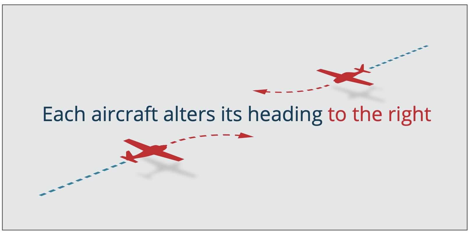
» When two aircraft are approaching head-on and there is a danger of collision, each aircraft should alter its heading to the right.
An aircraft that is about to take off must only do so when there is no apparent risk of collision with other aircraft.
» Pilots who are aware that an aircraft is compelled to land (for example, in case of an emergency) must give way to that aircraft.
OVERTAKING
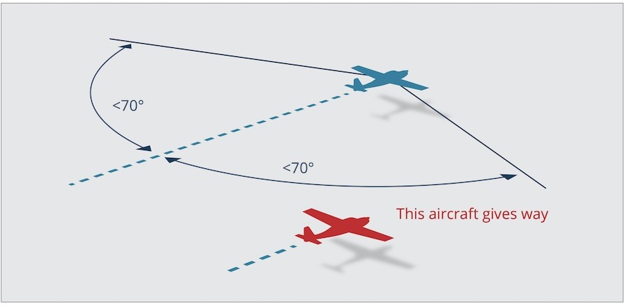
» An overtaking aircraft is defined as one that approaches another from the rear on a line forming an angle of less than 70° with the plane of symmetry of the other. That means an aircraft is considered to be overtaking if it is positioned in a way that would make it unable to see the forward navigation lights of the other aircraft at night.
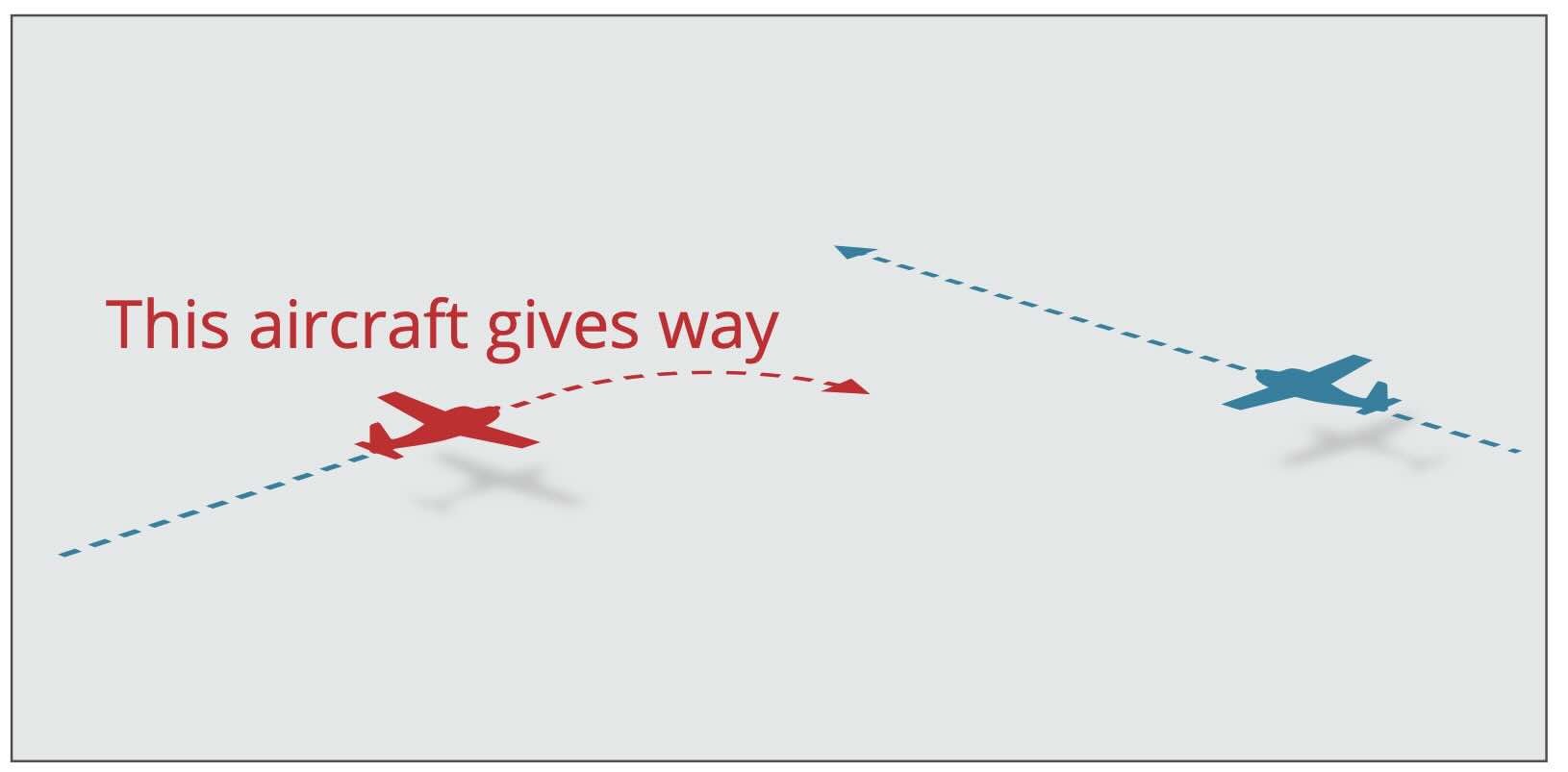
An aircraft that is being overtaken has right of way. Regardless of whether it is climbing, descending, or in horizontal flight, the aircraft that is overtaking must alter its heading to the right and keep out of the way of the other aircraft. Even if the relative positions of both aircraft change, the aircraft being overtaken retains right of way until the overtaking aircraft is entirely past and clear.
» An aircraft cannot dive or climb to overtake another.
Information provided by Australian Government, Civil Aviation Safety Authority


Discussion about this post